Product Description
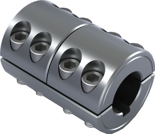
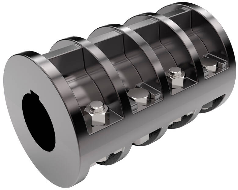
GHC Oldham type coupling cross sliding clamp coupling
Description of GHC Oldham type coupling cross sliding clamp coupling
>The colloid material is imported PA66, which has good wear resistance, corrosion resistance and electrical insulation
>Sliding design can compensate radial and angular deviation more effectively
>Detachable design, easy to install
>Fastening method of clamping screw
Dimensions of GHC Oldham type coupling cross sliding clamp coupling
| model parameter | common bore diameter d1,d2 | ΦD | L | LF | LP | F | M | tightening screw torque (N.M) |
| GHC-16X21 | 4,5,6,6.35 | 16 | 21 | 8.6 | 11.6 | 2.5 | M2.5 | 1 |
| GHC-16X30 | 4,5,6,6.35 | 16 | 30 | 13.1 | 11.6 | 3 | M2.5 | 1 |
| GHC-20X22 | 5,6,6.35,7,8 | 20 | 22 | 8.6 | 12.7 | 2.5 | M2.5 | 1 |
| GHC-20×33 | 5,6,6.35,7,8 | 20 | 33 | 14.1 | 12.7 | 3 | M2.5 | 1 |
| GHC-25×28 | 5,6,6.35,8,9,9.525,10,11,12 | 25 | 28 | 11.7 | 16.65 | 3 | M3 | 1.5 |
| GHC-25X39 | 5,6,6.35,8,9,9.525,10,11,12 | 25 | 39 | 17.2 | 16.65 | 4.2 | M3 | 1.5 |
| GHC-32X33 | 5,6,8,9,9.525,10,11,12.12.7,14,15,16 | 32 | 33 | 14 | 19.5 | 3 | M4 | 2.5 |
| GHC-32X45 | 5,6,8,9,9.525,10,11,12,12.7,14,15,16 | 32 | 45 | 20 | 19.5 | 4.5 | M4 | 2.5 |
| GHC-40X50 | 8,9,9.525,10,11,12,14,15,16,17,18,19 | 40 | 50 | 23 | 18.4 | 7 | M5 | 7 |
| GHC-45X46 | 8,9,9.525,10,11,12,14,15,16,17,18,19,20,22 | 45 | 46 | 21 | 18.4 | 7 | M5 | 7 |
| GHC-50X53 | 10,11,12.7,14,15,16,17,18,19,20,22,24 | 50 | 53 | 24 | 15 | 7.5 | M6 | 12 |
| GHC-50X58 | 10,11,12.7,14,15,16,17,18,19,20,22,24 | 50 | 58 | 26.5 | 17.5 | 8 | M6 | 12 |
| GHC-55X57 | 10,11,12.7,14,15,16,17,18,19,20,22,24,25,28,30,32 | 55 | 57 | 26 | 17.5 | 7.8 | M6 | 12 |
| GHC-63X71 | 14,15,16,17,18,19,20,22,24,25,28,30,32 | 63 | 71 | 33 | 24 | 10 | M8 | 20 |
| GHC-70X77 | 14,15,16,17,18,19,20,22,24,25,28,30,32,35,38 | 70 | 77 | 29.5 | 25 | 12 | M8 | 20 |
| model parameter | Rated torque (N.M)* |
allowable eccentricity (mm)* |
allowable deflection angle (°)* |
allowable axial deviation (mm)* |
maximum speed rpm |
static torsional stiffness (N.M/rad) |
moment of inertia (Kg.M2) |
Material of shaft sleeve | Material of shrapnel | surface treatment | weight (g) |
| GHC-16X21 | 0.7 | 0.8 | 3 | ±0.2 | 8500 | 30 | 5.5×10⁻⁷ | High strength aluminum alloy | P A 6 6 | Anodizing treatment | 8 |
| GHC-16X30 | 0.7 | 0.8 | 3 | ±0.2 | 9000 | 30 | 5.9×10⁻⁷ | 12 | |||
| GHC-20X22 | 1.2 | 1.2 | 3 | ±0.2 | 6500 | 58 | 1.3×10⁻⁶ | 13 | |||
| GHC-20×33 | 1.2 | 1.2 | 3 | ±0.2 | 7000 | 58 | 1.5×10⁻⁶ | 19 | |||
| GHC-25X28 | 2 | 1.6 | 3 | ±0.2 | 5500 | 130 | 4.0×10⁻⁶ | 24 | |||
| GHC-25X39 | 22 | 1.6 | 3 | ±0.2 | 6000 | 130 | 4.5×10⁻⁶ | 35 | |||
| GHC-32X33 | 4.5 | 2 | 3 | ±0.2 | 4500 | 270 | 1.3×10⁻⁵ | 48 | |||
| GHC-32X45 | 4.5 | 2 | 3 | ±0.2 | 4800 | 270 | 1.5×10⁻⁵ | 67 | |||
| GHC-40X50 | 9 | 2.4 | 3 | ±0.2 | 3600 | 520 | 4.2×10⁻⁵ | 114 | |||
| GHC-45X46 | 12 | 2.5 | 3 | ±0.2 | 3500 | 800 | 4.5×10⁻⁵ | 140 | |||
| GHC-50X53 | 19 | 2.6 | 3 | ±0.2 | 3000 | 800 | 1.0×10⁻⁴ | 190 | |||
| GHC-50X58 | 19 | 3 | 3 | ±0.2 | 3000 | 800 | 1.1×10⁻⁴ | 215 | |||
| GHC-55X57 | 25 | 3.2 | 3 | ±0.2 | 3000 | 900 | 1.3×10⁻⁵ | 260 | |||
| GHC-63X71 | 33 | 3 | 3 | ±0.2 | 2550 | 1200 | 3.5×10⁻⁴ | 455 | |||
| GHC-70X77 | 56 | 3.5 | 3 | ±0.2 | 2500 | 1260 | 4.1×10⁻⁵ | 520 |
/* January 22, 2571 19:08:37 */!function(){function s(e,r){var a,o={};try{e&&e.split(“,”).forEach(function(e,t){e&&(a=e.match(/(.*?):(.*)$/))&&1

How do Clamp Couplings Contribute to Reducing Backlash and Resonance in Rotating Machinery?
Clamp couplings play a crucial role in reducing backlash and resonance in rotating machinery, enhancing the overall performance and reliability of the system. Here’s how they achieve this:
1. Backlash Reduction:
Backlash is the play or clearance between mating components in a mechanical system. In rotating machinery, backlash can lead to lost motion, reduced precision, and inefficiencies. Clamp couplings offer several features that help minimize backlash:
- Zero-Backlash Design: Some clamp couplings are designed with a split hub and a clamping mechanism that ensures a tight fit around the shafts. This zero-backlash design eliminates any clearance between the coupling and the shafts, reducing or even eliminating backlash.
- High Clamping Force: Clamp couplings exert a strong clamping force on the shafts, ensuring a secure and rigid connection. This prevents any relative movement between the coupling and the shafts, further reducing backlash.
2. Resonance Damping:
Resonance occurs when the natural frequency of a rotating system matches the frequency of external forces or disturbances. This can lead to excessive vibrations and potential damage to the machinery. Clamp couplings can help dampen resonance in the following ways:
- Material Selection: High-quality materials like stainless steel or aluminum alloy are commonly used in clamp couplings. These materials possess excellent damping properties, dissipating vibrations and minimizing resonance effects.
- Precision Machining: Clamp couplings are precisely machined to maintain balance and reduce vibration during operation. Balanced couplings minimize the likelihood of resonant frequencies being excited, contributing to a smoother operation.
- Torsional Stiffness: Clamp couplings offer controlled torsional stiffness, which helps prevent the buildup of excessive vibration amplitudes and reduces resonance occurrences.
3. Misalignment Compensation:
Another factor contributing to backlash and resonance is misalignment between shafts. Clamp couplings can accommodate a certain degree of angular, parallel, and axial misalignments, reducing the impact of misalignment-induced backlash and vibrations.
Overall, clamp couplings provide a secure and precise connection between shafts, minimizing backlash and resonance in rotating machinery. By choosing the appropriate clamp coupling based on the specific requirements of the application, engineers can optimize the performance and efficiency of the rotating system.
Clamp Couplings and Damping Vibrations/Noise
Yes, clamp couplings can help dampen vibrations and reduce noise in mechanical systems to some extent. While not specifically designed as vibration isolators, clamp couplings can mitigate vibrations and noise due to their unique design and material properties.
The design of clamp couplings involves a split hub with screws that securely fasten around the shafts. This design offers several benefits:
- Damping Effect: The material of the coupling can absorb and dampen some of the vibrations generated by rotating equipment. Elastomeric elements or flexible materials used in some clamp couplings can help attenuate vibrations.
- Reduction of Resonance: Vibrations in rotating machinery can sometimes lead to resonance, causing excessive oscillations. Clamp couplings can help break the resonance cycle and prevent amplification of vibrations.
- Torsional Compliance: Some clamp couplings exhibit a degree of torsional compliance, which means they can tolerate small angular misalignments and dampen torsional vibrations.
- Transmissible Torque Variation: In some cases, clamp couplings can absorb torque spikes or variations, reducing the impact of sudden changes in load.
While clamp couplings can provide some level of vibration and noise reduction, their primary function is to transmit torque and accommodate misalignment between shafts. For more demanding vibration isolation or noise reduction applications, specialized components such as flexible couplings with damping features or dedicated vibration isolation mounts may be more suitable.
It is essential to consider the specific requirements of the mechanical system and consult with experts to determine the most appropriate coupling or isolator for achieving the desired level of vibration and noise reduction.
Handling Misalignment with Clamp Couplings
Yes, clamp couplings are designed to handle certain degrees of misalignment between shafts effectively. They can accommodate both angular and parallel misalignments, making them versatile for various mechanical systems.
The design of clamp couplings allows for a certain degree of flexibility and forgiveness in the coupling’s connection. When the shafts are not perfectly aligned due to angular or parallel misalignment, the clamp coupling can compensate for these variations.
The main factors contributing to the clamp coupling’s ability to handle misalignment are:
- Flexible Material: Clamp couplings are often made of materials like aluminum, stainless steel, or other alloys with some elasticity. This flexibility enables them to absorb and compensate for minor misalignments.
- Split Design: Clamp couplings usually have a split design with one or more screws or bolts that can be tightened to secure the coupling around the shafts. This design allows for easy installation and adjustment, making it possible to accommodate slight misalignments during assembly.
- Tightening Mechanism: The screws or bolts used to fasten the clamp coupling can be tightened to the appropriate torque, providing a secure connection while still allowing for a certain amount of movement to handle misalignment.
However, it’s important to note that clamp couplings have limitations when it comes to misalignment. Excessive misalignment can lead to increased wear on the coupling components and shafts, reducing the coupling’s lifespan and potentially causing failure. Therefore, it’s essential to ensure that the misalignment does not exceed the coupling’s specified limits.
For more significant misalignments or applications with constant large misalignments, flexible couplings like elastomeric couplings or gear couplings may be more suitable. It’s crucial to select the appropriate coupling type based on the specific misalignment requirements of the mechanical system.
In conclusion, while clamp couplings can handle certain degrees of misalignment effectively, it is essential to stay within the recommended misalignment limits to maintain the coupling’s performance and longevity.


editor by CX 2024-03-15