Diaphragm coupling
Drum gear coupling
Plum-shaped elastic coupling
Star coupling
Elastic pin coupling
Elastic pin gear coupling
Elastic sleeve pin coupling
JQ type clamp coupling
Sprocket coupling
Slider coupling
Tyre coupling
Rigid coupling
Serpentine spring coupling
Three-jaw coupling for pump
Coupling accessories
Coupling rough
LK elastic block coupling
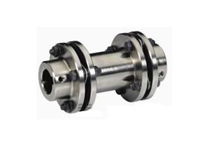
JMIJ type connecting intermediate shaft type diaphragm coupling
The JMIJ type intermediate shaft diaphragm coupling can compensate for the axial, radial and angular deviations between the driving machine and the driven machine due to manufacturing errors, installation errors, load-bearing deformations and the effects of temperature rise changes. The JMIJ type diaphragm coupling is a flexible coupling with metal elastic elements. It relies on the metal coupling diaphragm to connect the main and driven machines to transmit torque. It has the advantages of elastic vibration damping, no noise, and no need for lubrication. It is an ideal product to replace gear couplings and general couplings. JMIJ type diaphragm coupling shafting transmission system: shafting transmission usually consists of one or several JMIJ type diaphragm couplings connecting the main and driven shafts to form a shafting transmission system to transmit rotation or movement. The JMIJ diaphragm coupling is mainly due to the shaft connection of the motor, reducer and working machine. Its shaft hole form, connection form and size mainly depend on the type and size of the connected shaft. The product design is generally cylindrical and conical Shaft depth standard design shaft, shaft depth standard is for shaft design.
Performance of JMIJ type diaphragm coupling with intermediate shaft
1. The film stress produced by the torque of the JMIJ type connecting intermediate shaft type diaphragm coupling.Suppose the transmitted torque is T(Nm), and the total number of pieces is m. For 8-hole bolts, it is known from simplified conditions: the torque of a single diaphragm is T1=T/m, and the force on each main bolt is F =T/4mR.
2. The bending stress caused by the angular installation error of the JMIJ diaphragm coupling can be simplified to solve the actual error of the installation in the axial angular direction, which causes the diaphragm to periodically bend and deform in the axial direction, and it determines the coupling The main reason for the fatigue life of the diaphragm is calculated according to the angular deviation caused by the displacement of the middle bolt hole in the axial direction. The radial displacement and the axial displacement of the JMIJ diaphragm coupling are fixed. The restoring moment H can be obtained by the angle inclination Under normal circumstances, the angular displacement of the coupling diaphragm is very small, so the diaphragm deformation is a small deformation, which can be analyzed by the small deflection bending theory of the thin plate.
JMIJ type diaphragm coupling installation instructions
1. Before installation, check whether the two shafts of the prime mover and the working machine are concentric, whether there are wrapping paper and scratches on the surfaces of the two shafts, whether there are debris in the inner holes of the two half couplings of the coupling, and whether the edges of the inner holes are bumped. If there is any damage, the shaft and half coupling should be cleaned up, and the damage should be treated with a fine file.Then check whether the inner hole diameter and length of the two half couplings are consistent with the diameter and shaft elongation of the prime mover and working machine.In general selection, it is better to make the length of the prime mover and the working machine end half coupling less than its shaft elongation 10-30mm.
2. In order to facilitate the installation, it is best to put the two half couplings in the 120-150 incubator or oil tank for preheating, so that the size of the inner hole is enlarged and it is easy to install.After installation, the shaft head should not protrude from the end face of the half coupling, it is better to be flush.Detect the distance between the two halves of the coupling: take the average of the readings of 3 to 4 points measured along the two inner sides of the flange of the half coupling, and the sum of the measured dimensions of the extension and the two diaphragm sets, two The error is controlled within the range of 0-0.4mm.
3. 找正:用百分表检测两半联轴节法兰盘端面和外圆跳动,当法兰盘外圆小于250mm时跳动值应不大于0.05mm;当法兰盘外圆大于250mm时,跳动值应不大于0.08
Refer to table for measurement method
| model | Nominal torque Tn /Nm | Instantaneous large torque Tmax /Nm | Permissible speed [n] /r.min-1 | Axle hole diameter d (H7) | Shaft hole shaft hole shaft hole shaft hole | D | t | L2 | Moment of inertia I/kg.m2≈ | Mass m/kg ≈ | |||
| Y type | J, J1, Z, Z1型 | L recommended | |||||||||||
| L | L | L1 | |||||||||||
| JMIJ1 | 25 | 80 | 6000 | 14 | 32 | - | J1Type 27 Z1Type 20 | 35 | 90 | 8.8 | 100 | 0.0013 | 1.8 |
| 16, 18, 19 | 42 | 30 | |||||||||||
| 20, 22 | 38 | ||||||||||||
| JMIJ2 | 63 | 180 | 5000 | 18, 19 | 42 | - | 30 | 45 | 100 | 9.5 | 100 | 0.002 | 2.4 |
| 20, 22, 24 | 52 | 38 | |||||||||||
| 25 | 62 | 44 | |||||||||||
| JMIJ3 | 100 | 315 | 5000 | 20, 22, 24 | 52 | - | 38 | 50 | 120 | 11 | 120 | 0.0047 | 4.1 |
| 25, 28 | 62 | 44 | |||||||||||
| 30 | 82 | 60 | |||||||||||
| JMIJ4 | 160 | 500 | 4500 | 24 | 52 | - | 38 | 55 | 130 | 12.5 | 120 | 0.0069 | 5.4 |
| 25, 28 | 62 | 44 | |||||||||||
| 30, 32, 35 | 82 | 60 | |||||||||||
| JMIJ5 | 250 | 710 | 4000 | 28 | 62 | - | 44 | 60 | 150 | 14 | 140 | 0.0153 | 8.8 |
| 30-32-35 | 82 | 60 | |||||||||||
| 40 | 112 | 84 | |||||||||||
| JMIJ6 | 400 | 1120 | 3600 | 32, 35, 38 | 82 | 82 | 60 | 65 | 170 | 15.5 | 140 | 0.0281 | 13.4 |
| 40, 42, 45, 48, 50 | 112 | - | 84 | ||||||||||
| JMIJ7 | 630 | 1800 | 3000 | 40, 42 | 112 | 112 | 84 | 70 | 210 | 19 | 150 | 0.076 | 22.3 |
| 45, 48, 50, 55, 56 | |||||||||||||
| 60 | 142 | 107 | |||||||||||
| JMIJ8 | 1000 | 2500 | 2800 | 45, 48 | 112 | 112 | 84 | 80 | 240 | 22.5 | 180 | 0.1602 | 36 |
| 50, 55, 56 | |||||||||||||
| 60-63-65 | 142 | 107 | |||||||||||
| JMIJ9 | 1600 | 4000 | 2500 | 55, 56 | 112 | 112 | 84 | 85 | 260 | 24 | 220 | 0.2509 | 48 |
| 60, 63, 65, 70, 71, 75 | 142 | 107 | |||||||||||
| 80 | 172 | 132 | |||||||||||
| JMIJ10 | 2500 | 6300 | 2000 | 63, 65, 70, 71, 75 | 142 | 142 | 107 | 90 | 280 | 17 | 250 | 0.5195 | 85 |
| 80-85-90 | 172 | - | 132 | ||||||||||
| JMIJ11 | 4000 | 9000 | 1800 | 75 | 142 | 142 | 107 | 95 | 300 | 19.5 | 290 | 0.8223 | 112 |
| 80-85-90 | 172 | 172 | 132 | ||||||||||
| 100, 110 | 212 | - | 167 | ||||||||||
| JMIJ12 | 6300 | 12500 | 1600 | 90, 95 | 172 | 132 | 120 | 340 | 23 | 300 | 1.4109 | 152 | |
| 100-110-120 | 212 | 167 | |||||||||||
Hangzhou JMIJ type connecting intermediate shaft type diaphragm coupling Hangzhou JMIJ type connecting intermediate shaft type diaphragm coupling