The wear problem of the drum gear coupling and the matters needing attention in adjustment and alignment
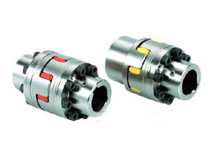
Product features and wear problems of drum gear couplings
XNUMX. The product characteristics of drum gear couplings mainly include the following aspects
1. Strong carrying capacity.Under the same outer diameter of the inner gear sleeve and the large outer diameter of the coupling, the carrying capacity of the drum gear coupling is 15-20% higher than that of the straight gear coupling on average;
2. Large angular displacement compensation.When the radial displacement is equal to zero, the allowable angular displacement of the spur gear coupling is 1; while the allowable angular displacement of the drum gear coupling is 1:30”, which is increased by 50%, in the same modulus, Under the number of teeth and tooth width, the allowable angular displacement of the drum gear is larger than that of the straight tooth;
3. The drum-shaped tooth surface makes the contact conditions of the inner and outer teeth avoid the disadvantages of squeezing the edge of the straight tooth and stress concentration under the condition of angular displacement. At the same time, it reduces the friction and wear of the tooth surface, reduces the noise, and maintains it. Long cycle
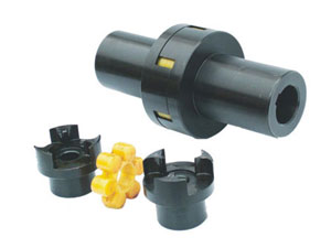
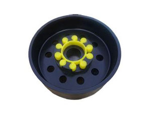
4. The tooth end of the outer gear sleeve is in the shape of a horn, which makes the assembly and disassembly of the inner and outer gears convenient.
5. Transmission.Based on the characteristics of the warp, drum-shaped teeth have generally been used instead of straight-tooth couplings.The specifications of drum gear couplings produced by some manufacturers meet the corresponding standards.Drum-shaped gear couplings are rigid, flexible, and inelastic, so they are not suitable for machinery that requires damping, buffering, and two-axis alignment.
XNUMX. For the wear problem of drum gear coupling, we can refer to the following aspects
1. Due to the mutual wear of the parts of the coupling during operation, the size changes and the damage occurs.This type of damage can generally be checked with measuring tools.Commonly used measuring tools include vernier calipers and micrometers with precision 0.01mm-0.02mm.
2. Due to the overheating and extrusion of the parts of the coupling during operation, the mechanical properties of the surface change and cause damage.For this type of damage, tools such as files, abrasive blocks, or other instruments are used to determine the hardness change of the surface layer, and the extrusion of the parts can be observed with eyes.When these defects exist, even if the wear of the size and shape of the part does not exceed the allowable range, depending on the impact of the mechanical properties of the surface layer on the coupling, sometimes the part must be deemed scrapped.
3. Due to the external force acting on the parts of the coupling during operation, the parts will be bent, twisted, elliptical or other special-shaped changes. This change is usually called the exact geometric shape loss of the parts.The measurement method of this type of damage is basically the same as the first type of measurement method.The deformation of parts such as bending can sometimes be checked with a dial indicator on a lathe.
4. Damage to other surfaces, such as erosion and erosion.This type of damage is generally observed with eyes.It is mainly to determine whether the degree of damage and the resulting dimensional changes are within the allowable range of the quality requirements, and then determine whether the part is scrapped or scrapped.
Three, several matters needing attention when adjusting and aligning the drum gear coupling
1. If the concentricity of the coupling is tested before the anchor bolts are tightened, there is no need to rush to remove the measuring tool after adjustment.Because in the process of tightening the anchor bolts, due to improper tightening method, or the shim near the anchor bolts are not really supported, etc., the installation accuracy after tightening will change.Generally, it is required to check again after tightening, or check while tightening, with the concentricity of the two shafts.
2. When installing on site, due to the limitation of conditions, most of the pad irons used to adjust the level are iron plates of different thickness.When in use, clean the burrs, welding slag and other debris on the edge of the iron plate to prevent the debris from breaking due to vibration and other reasons after the adjustment of the parts, the shim support is not strong, the parts sink or the position changes , So that the concentricity of each coupling changes, causing the equipment installation accuracy to fail to meet the requirements.Generally, after the adjustment meets the requirements, the pad iron is welded into a whole.
3. When installing, install the roller components first, and then use the roller spindle as the reference axis to measure the concentricity between the output shaft of the reducer and the roller spindle.After the reducer components are adjusted to meet the requirements, the concentricity of the motor shaft is measured with the input shaft of the reducer as the reference axis.However, because the brake wheel coupling is installed on the input shaft of the reducer, both the motor and the brake are installed on the motor base.Before adjusting the motor shaft, take the brake wheel table as the reference. After adjusting the brake shoe on the brake, adjust the concentricity of the motor shaft and the input shaft of the reducer.When the torque is sufficient to overcome the operation load, the turbine starts to rotate and drives the conveyor to run through the reducer.