The stress distribution of diaphragm coupling and its improvement method
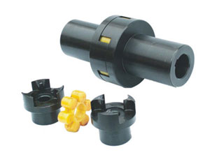
Diaphragm coupling is a transmission device that uses metal flexible components to transmit torque without lubrication. It is widely used in ships, aviation, petrochemical, machinery manufacturing and other fields.The flexible element is a diaphragm group composed of a number of thin metal diaphragms of 0.2mm~0.6mm.When working, the torque is input from the active flange, and the torque is transmitted to the metal diaphragm through the active torsion bolts arranged at intervals along the circumference, and then the diaphragm is transmitted to the driven flange through the driven bolts for output.It realizes the flexible transmission of the coupling through the elastic deformation of the alloy diaphragm group, and uses the flexibility of the diaphragm to absorb the relative displacement between the input and output shafts, thereby compensating for the residual errors caused by various factors in the various connecting parts of the transmission shaft system. in.
The misalignment forms that the diaphragm coupling can compensate include the following three basic types: angular (the center lines of the two shafts intersect at the midpoint between the ends of the two shafts at an angle), transverse (the center lines of the two shafts are offset in parallel) and Axial (excessive axial clearance between the two shafts).The actual offset that occurs during the operation of the rotating shaft system is often a combination of any of the above two types of misalignment or three types of misalignment at the same time, so the load and deformation of the diaphragm coupling during actual work are more complicated.
As the key elastic element of the diaphragm coupling, the diaphragm bears the main load during operation.
When the diaphragm coupling rotates, its angular deviation will produce alternating stress, which alternates once per rotation.The dynamic stress of the diaphragm will cause the fatigue damage of the diaphragm and the bolt, so the accurate calculation of the dynamic and static composite stress is the key to predict the life of the diaphragm coupling and the work of the diaphragm coupling.
The existing related research is mostly limited to the analysis of the stress distribution of the diaphragm when it is subjected to a certain load alone, while the dynamic and static composite stress when the diaphragm is actually subjected to a complex load is rarely involved.
The membrane segment between two adjacent bolt holes can be equivalent to a cantilever beam, and the method of material mechanics is used to deduce that the connecting rod diaphragm coupling can bear torque, centrifugal load, axial offset, and angular deviation independently. The calculation formula for the internal stress of the diaphragm is shifted, and a method for calculating the torsional stiffness of the diaphragm is proposed. It is a typical method to analyze the stress and stiffness of the diaphragm by using an empirical formula, but its shortcoming is that the stress in the area around the bolt hole cannot be considered. The influence of the concentration effect causes a large gap between the calculated stress and the actual stress.
A typical study on diaphragm stress and fatigue life using finite element method and thin plate bending theory.The common point is to first analyze the stress of the diaphragm under various individual working conditions, and use the combined stress of the three static stresses (axial bending stress, diaphragm stress, and centrifugal stress) as the average stress of the diaphragm, and the rotation angle The stress caused by the offset is regarded as the alternating stress amplitude, and the average stress and the alternating stress amplitude are obtained by static analysis, and then the fatigue analysis is carried out based on this result.However, the above research methods need to be improved in two points:
1. Generally speaking, the distribution of static combined stress and the distribution of angular bending stress are different.Strictly speaking, the areas of stress point distribution do not overlap in the two cases.
2. In addition to centrifugal force, rotation also generates inertial force.Regarding the stress generated by angular offset as the alternating stress amplitude actually ignores the influence of inertial force.
We conducted research on these two points, taking the waist-type elastic diaphragm coupling that is common in engineering applications as an example, using the finite element software ANSYS to model, and introducing the transient dynamics analysis method into the stress analysis of the diaphragm coupling .The transient dynamics method is a method used to determine the dynamic response of a structure subject to any time-varying load. It can be analyzed to determine the structure's change with time under any combination of static load, transient load and simple harmonic load. Displacement, strain, stress and force, etc.